ROS 사용기 - (3) ROS Industrial

Research 2015. 7. 16. 11:12

Robot Teaching SW를 개발하다보니, ROS의 사용을 통해 훨씬 좋은 결과를 활용할 수 있음을 알게 되었고

그러다 또 찾은 것은 이미 이를 산업 현장에 적용하고자 노력하는 컨소시움이 형성되어있음을 알 수 있었다.


그 이름은 바로 ROS Industrial.. 2012년 1월에 SW는 GoogleCode에 공유 되었고(현재는 GitHub), 

2013년 3월 Shaun Edwards에 의해 ROS Industrial 컨소시움은 출범한다. 

ROS Industrial의 기원은 이런 곳에서 출발한다.

" 산업용 로봇 시장은 매우 커졌지만, 아직 수행하는 Task의 종류는 몇 가지로 한정되어 있다. 20년간 많은 연구비가 새로운 Task의 연구를 위해 투자되었지만, 연구실에서 연구한 내용은 실제 현장에 적용하기 어렵다. 우리는 연구실의 연구 내용을 실제 현장에 적용할 수 있는 방법을 제공하고자 한다. "

아래의 Youtube 영상을 보면 내가 하고자 하는 것들의 현실에 대해서 파악할 수 있었다..!!


https://www.youtube.com/watch?t=225&v=xenFvis_iVc

https://www.youtube.com/watch?v=GoAS9bmlenA 

https://www.youtube.com/watch?v=Ek8GKqmJ7n0 

https://www.youtube.com/watch?v=5zO46F1xEzk 

https://www.youtube.com/watch?v=eMlGV94c5WU 


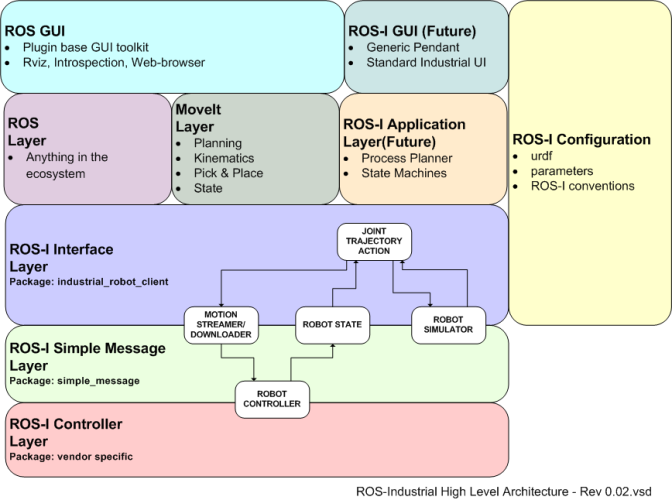
ROS Industrial의 구조..


그리고 내가 연구하기에 좋은 staubli 에 관련된 SW 내용은

http://wiki.ros.org/staubli

에서 찾아볼 수 있다!

(두*로보틱스에서 원하던 Calibration 관련 기능의 단서를 Industrial Calibration package(에서 얻을 수 있지 않을까!?! http://rosindustrial.org/videos/#Industrial Calibration Library )


트레이닝은 (http://aeswiki.datasys.swri.edu/rositraining/indigo/Exercises/) 에서 하자!


* Ref 

[1] http://rosindustrial.org/


설정

트랙백

댓글

ROS 사용기 - (2) ROS 설치

Research 2015. 7. 13. 18:39

앞에서와 같은 우분투의 upgrade를 마쳤음에도 불구하고 http://wiki.ros.org/indigo/Installation/Ubuntu 에 나온대로 설치하면 뭔가 안되는 문제가 발생한다. (아마도 이유는 repository 주소가 잘못되는듯..)

최종적으로는 unable to locate package ros-indigo-desktop-full 라는 에러 메시지를 얻는다.


그래서 googling을 한 결과! 아래와 같은 좋은 정보를 얻을 수 있었고, 성공적으로 ros indigo를 설치할 수 있었다!! (ref: http://answers.ros.org/question/188732/e-unable-to-locate-package-ros-indigo-desktop-full/)

sudo sh -c 'echo "deb http://packages.ros.org/ros/ubuntu trusty main" > /etc/apt/sources.list.d/ros-latest.list'

wget https://raw.githubusercontent.com/ros/rosdistro/master/ros.key -O - | sudo apt-key add -

sudo apt-get update

sudo apt-get install ros-indigo-desktop-full

자 이제 아래의 과정만 거치면 된다!!

apt-cache search ros-indigo


echo "source /opt/ros/indigo/setup.bash" >> ~/.bashrc
source ~/.bashrc


그런데 중간에 echo "source /opt/ros/indigo/setup.bash" >> ~/.bashrc 부분에서 setup.bash를 setup.bach 로 오타를 치는 실수가 발생...


그래서 ~/.bash 파일을 수정해 주어야 할 필요가 있었다...

일단 ~/.bash 파일은 기본적으로 hidden이 되어 있기 때문에 GUI에서는 보이지 않는다.! ㅠ

vi를 통해 수정을 해볼까 했는데.. vi 사용이 처음이라 그런 지 어색하고 어려웠다..


vi 사용법은 아래에서 참고했다.

(문자 수정하는 게 이렇게 어려울 줄이야..)

http://neoted.tistory.com/entry/vi-%EC%82%AC%EC%9A%A9%EB%B2%95-%EA%B0%84%EB%9E%B5-%EC%A0%95%EB%A6%AC-%EB%B2%84%EC%A0%BC


source /opt/ros/indigo/setup.bash

그래서 위의 과정을 무사히 마치고, (command 창에는 아무 말도 안나온다.)

sudo apt-get install python-rosinstall

위의 과정을 마침으로써 이제 Ros 설치는 완성~!!!


그런데 한국의 ros wiki (http://www.ros.or.kr/index.php/Install_ros) 를 보니 아래의 과정도 거치라고 한다.

$ sudo apt-get install python-rosdep python-wstool python-rosinstall python-rospkg

그런데 일단 나중에 해도 될 것 같아서 여기에 기록만 해 두고 넘어간다!


이제 아래와 같이 command line에 roscore 를 입력해 주었을 때 error message가 없이 잘 나온다면 성공!


설정

트랙백

댓글

ROS 사용기 - (1) Linux 설치

Research 2015. 7. 12. 23:29

그 동안 Robot 의 easy teaching을 위해 C++와 MFC로 무한 개발의 늪에 빠져 있었다..

Robot의 추상화, robotic algorithm, Teaching SW library, 등..

특히 robotics algorithm은 최적화 된 algorithm이 아님에도 불구하고 굉장히 많은 시간을 요한다.

(이러다 시뮬레이터 하나 개발하겠어~ 라는 느낌이 들더라는!)


그! 래! 서! 인터넷을 검색해 보았는데 결국.. 아래와 같은 멋진 영상을 보게 된다.

https://www.youtube.com/watch?v=IfP6J9Bxt2w

https://www.youtube.com/watch?v=vylvdHeoxWA   (특히 이 영상은 나에게 더욱 눈물을 안겨준다..)

사실 내가 구현을 하고 있던 내용이 이미 완성되어 있었다는 좌절감... 과 함께 

time consuming 그만하고 OpenSource를 활용해 더 나은 SW를 만들어 보겠어!! 라는 희망을 느껴본다!!

( 심지어 BSD 라이센스라서 원할 경우 상업용으로 재배포 가능하다. 물론 모두를 위해 open 하는 것이 좋겠지! )


우선 오늘은 주말이니 가족과 함께 시간을 보낸 후..

(특히 아들 녀석과 놀아줘야 해서 키즈 카페에서 한바탕 뛰어다녔다.)


모두가 잠든 이 고요한 시각에 예전에 사용하던(이젠 너무 구형이 되어버린..ㅠ) 64GB SSD 를 꺼내어 본다!

그래, 이곳에 Ubuntu를 설치하고 ROS 사용의 초석을 다져보겠어!


물론 집에서 얼마나 열심히 할 수 있을 지는 모르겠지만... 일단 설치는 완료했다.

내가 참고한 사이트는 아래와 같다. 아래 글만큼 정리를 잘 할 자신은 없고, 일단 reference를 달아 본다.


* Ref

[1] http://blog.naver.com/bb_/220394881339

[2] http://blog.naver.com/kimmy5000?Redirect=Log&logNo=220298448745


아, 연구실 컴퓨터는 VM ware를 사용하고 있고, 일전에 Ubuntu 12.04 LTS를 설치한 적이 있다.

그래서 upgrade 메시지가 자동으로 떠서 확인을 눌러 주었는데... 시간이 엄청나게 오래 걸린다.

그냥 새로 설치하는 것이 나을 뻔 했다.. ㅠㅠ


설정

트랙백

댓글

Aliasing

Research/Robot Vision 2015. 6. 29. 10:35

aliasing은 image scaling을 시도할 때 발생한다. 

아래 사진을 보면, 이미지를 간단한 방식(image decimation)으로 suibsampling 했더니 이상한 패턴(aliasing)이 발생한다.

왜 발생하는 것일까?


신호처리에서 배웠던 nyquist thorem을 돌이켜 보자. 

만약, 우리의 image가 2pixel을 주기로 intensity 신호를 갖는다면, 우리는 충분한 주기(4 pixel)로 샘플링을 해 주어야 같은 신호를 얻을 수 있다. 

그렇지 않으면..  It will be confused with a low frequency signal after we have sampled.


aliasing을 제거하기 위해서는 image에서 high frequency 성분을 제거해야 한다. 

The way to eliminate this alias in problem is to remove the high frequency components from the image 


방법으로는 우선 Gaussian kernel을 통해 blurring을 한 후에 subsampling을 하면 된다. 


* Ref

[1] https://moocs.qut.edu.au/courses/791/learn


설정

트랙백

댓글

[OpenGL] 3D coordinates from 2D mouse click ( Convert Screen Coordinate to World Coordinate )

Skills/Programming 2015. 6. 22. 17:59


[1]

GLpoint GetOGLMousePos(GLint x, GLint y)
{
GLfloat winX = 0.0, winY = 0.0, winZ = 0.0;	   // never ever make a mistake between float and double.
I wasted my 4 days to solve this and the problem was, I was using GLdouble here instead of GLfloat.
Try GLdouble here you will see a hell difference in output values.


GLdouble posX = 0.0, posY = 0.0, posZ = 0.0;
winX = (float)x;
winY = (float)OGLMviewport[3] - (float)y;   // invert winY so that down lowers value
glReadPixels( x, int(winY), 1, 1, GL_DEPTH_COMPONENT, GL_FLOAT, &winZ );
gluUnProject( winX, winY, winZ, OGLMmodelview, OGLMprojection, OGLMviewport, &posX, &posY, &posZ);
return GLpoint(posX, posY, -posZ); // invert z value
}


[2]

private void glControl1_MouseClick(object sender, System.Windows.Forms.MouseEventArgs e)
        {
            if (!loadedTK) return; // Play nice   
 
            int[] viewport = new int[4];
            double[] modelViewMatrix = new double[16];
            double[] projectionMatrix = new double[16];
 
            if (checkBoxSelectPoints.Checked == true)
            {
                int mouseX = e.X;
                int mouseY = e.Y;
 
                //Get Matrix
                OpenTK.Graphics.OpenGL.GL.GetInteger(OpenTK.Graphics.OpenGL.GetPName.Viewport, viewport);
                OpenTK.Graphics.OpenGL.GL.GetDouble(OpenTK.Graphics.OpenGL.GetPName.ModelviewMatrix, modelViewMatrix);
                OpenTK.Graphics.OpenGL.GL.GetDouble(OpenTK.Graphics.OpenGL.GetPName.ProjectionMatrix, projectionMatrix);
 
                //Calculate NearPlane point and FarPlane point. One will get the two end points of a straight line
                //that "almost" intersects the plotted point you "clicked".
                Vector3 win = new Vector3(mouseX, viewport[3] - mouseY, 0);   
                Vector3 worldPositionNear;
                Glu.UnProject(win, modelViewMatrix, projectionMatrix, viewport, out worldPositionNear);
                win.Z = 1.0f;
                Vector3 worldPositionFar;
                Glu.UnProject(win, modelViewMatrix, projectionMatrix, viewport, out worldPositionFar);
 
                //Calculate the lenght of the straigh line (the distance between both points).
                double distanceNF = Math.Sqrt(Math.Pow(worldPositionNear.X - worldPositionFar.X, 2) + 
                                              Math.Pow(worldPositionNear.Y - worldPositionFar.Y, 2)+
                                              Math.Pow(worldPositionNear.Z - worldPositionFar.Z, 2));
                double minDist = distanceNF;
 
 
                 //Calculate which of the plotted points is closest to the line. In other words,
                // look for the point you tried to select. Calculate the distance between the 2 endpoints that passes through
                // each plotted point. The one that is most similar with the straight line will be the selected point.
                int selectedPoint = 0;
                for (int i = 0; i < PointsInfo.Count; i++)
                {
                    double d1 = Math.Sqrt(Math.Pow(worldPositionNear.X - PointsInfo[i].Position.X, 2) +
                                          Math.Pow(worldPositionNear.Y - PointsInfo[i].Position.Y, 2) +
                                          Math.Pow(worldPositionNear.Z - PointsInfo[i].Position.Z, 2));
 
                    double d2 = Math.Sqrt(Math.Pow(PointsInfo[i].Position.X - worldPositionFar.X, 2) +
                                          Math.Pow(PointsInfo[i].Position.Y - worldPositionFar.Y, 2) +
                                          Math.Pow(PointsInfo[i].Position.Z - worldPositionFar.Z, 2));
 
                    if (((d1 + d2) - distanceNF) <= minDist)
                    {
                        minDist = (d1 + d2) - distanceNF;
                        selectedPoint = i;
                    }
                }
 
                //Just select/unselect points if the "click" was really close to a point. Not just by clicking anywhere in the screen
                if (minDist < 0.000065)
                {
                    if (selectedPoints.Contains(selectedPoint))
                        selectedPoints.Remove(selectedPoint);
                    else
                        selectedPoints.Add(selectedPoint);
 
                    glControl1.Invalidate();  //paint again 
                }
            }


[3] 

private Vector3d GetOGLPos(int x, int y)
{
int[] viewport = new int[4];
double[] matrixprojection = new double[16];
double[] matrixmodeview = new double[16];
double WinX, WinY;
float[] WinZ = new float[1];
double PosX, PosY, PosZ;
IntPtr PixelPtr = System.Runtime.InteropServices.Marshal.AllocHGlobal(sizeof(float));

GL.glGetDoublev(GL.GL_PROJECTION_MATRIX, matrixprojection);
GL.glGetDoublev(GL.GL_MODELVIEW_MATRIX, matrixmodeview);
GL.glGetIntegerv(GL.GL_VIEWPORT, viewport);

GL.glEnable(GL.GL_DEPTH_TEST);
GL.glDepthMask(1);
GL.glDepthRange(0, 1);
System.Runtime.InteropServices.Marshal.Copy(WinZ, 0, PixelPtr, 1);

WinX = (double)x;
WinY = (double)viewport[3] - (double)y;
GL.glReadPixels(x, (int)WinY, 1, 1, GL.GL_DEPTH_COMPONENT, GL.GL_FLOAT, PixelPtr);

System.Runtime.InteropServices.Marshal.Copy(PixelPtr, WinZ, 0, 1);
System.Runtime.InteropServices.Marshal.FreeHGlobal(PixelPtr);

GL.gluUnProject(WinX, WinY,(double)WinZ[0], matrixmodeview, matrixprojection, viewport,out PosX,out PosY,out PosZ);
//PosZ = (double)WinZ[0];
Vector3d result = new Vector3d(PosX, PosY, PosZ);

return result;
}


* Ref

[1] http://www.gamedev.net/topic/632454-incorrect-3d-coordinates-from-2d-mouse-click/

[2] http://www.opentk.com/node/1892

[3] http://www.opentk.com/node/480


설정

트랙백

댓글

KB954430 자꾸만 다시 설치하라고 할 때..

Skills/Programming 2015. 6. 8. 11:28


아래 사이트를 참조하자.

https://social.technet.microsoft.com/Forums/windows/ko-KR/646651ca-1a32-46d3-bc5e-8d8a77eff9a7/update-kb954430?forum=w7itprogeneral

설정

트랙백

댓글

Deep learning pc building ( 딥러닝 컴퓨터 사양 )

Research/DeepLearning 2015. 6. 6. 00:57

요즘 떠오르는 대세인 딥 러닝!

딥러닝의 이론도 중요하지만, 우리에게는 이러한 이론을 학습시킬 머신 또한 중요하다! 

(무조건 좋은 사양보다는, 불필요한 비용(cost)은 최적화 된 사양을 맞추는 것이 좋겠다!)

그래서 열심히 웹 자료들을 뒤져서 좋은 사양을 찾아 소개할까 한다.


일단 GPU는 꼭 사용하도록 하자! 

(왜 GPU를 사용하는가?는 NVIDIA의 홈페이지에서 확인 가능하다. http://www.nvidia.com/object/what-is-gpu-computing.html )

(어떤 GPU를 사용해야하는가? 는 http://www.nvidia.com/object/what-is-gpu-computing.html  에 몹시 정리가 잘 되어 있다!)


결론부터 이야기 하자면, 


GPU : GTX titanX (향후 3~6년은 거뜬할 12GB의 메모리!!)

(Nvidia CEO에 의하면 TitanX가 메모리를 많이 필요로 하는 deep learning에 특화되었다고 한다! [4])

(심지어 GTC 2015에서 TitanX를 강력 추천 때리기도..!! [5])

(GPU benchmark에 의하면 980Ti 가 성능이 더 좋은 것으로 나오긴 하지만.. 코어도 메모리도 titanX가 앞선다. (2816 -> 3,072, 6GB->12GB)


CPU : 

최근 새로 나온 하스웰 CPU들은 PCIe를 충분히 지원하지 않는 경우가 있으니 주의해야 한다.
(참고로 요새 많이 쓰이는 5820K 는 40이 아닌 28 , 4790K는 16 lane만 제공한다. 충분하지 않은 이유는 [6] 에서 참조하자!)

(그리고 마더보드의 PCIe 버전과 호환되는 지 확인!)

CPU 캐쉬 사이즈는 크게 중요하지는 않다.


RAM : 

asynchronous mini-batch allocation <- 요게 필수!

GPU 램보다 많게 유지하는 것도 중요함.

clock이나 크게 중요치 않다.


Hard/SSD : 

충분한 여유 공간을 남기도록 한다.


POWER : 

파워는 충분히

GPU(들)에 필요한 Watt + CPU에 필요한 Watt + 100~300 Watt

기왕이면 efficiency rate이 좋은 것이 아무래도 좋겠지!


Cooling : 

생각보다 cooling이 중요하다. Deep learning 연산 중 GPU의 온도는 금새 뜨거워지는데, GPU는 온도를 유지하기 위해 자체적으로 속도를 느리게 만들기 때문이다. BIOS 셋업을 통해 fan speed를 최고로 올리거나 (소음을 견딜 수 있다면..) 수냉 방식의 쿨러를 추가하는 방법(조금 어렵지만)이 있다. 


Motherboard : 

기본적으로 우리가 선택한 요소들이 호환되는 보드
GPU를 여러 개 사용하고 싶다면 충분한 PCIe 포트(3.0 으로!!)가 있는 것을 사용 (아직은 보통 4개의 GPU가 한계)
일반적으로 GPU의 크기가 상당한(2 포트를 차지할 정도로..) 경우가 많으므로 우리는 7개 이상의 포트가 준비된 마더보드가 좋겠다.


CASE : 

GPU 가 충분히 들어갈 공간
왠만하면 GPU가 위 쪽에 위치하면 좋겠다
나중에 수냉식 쿨러를 장착하게 될 지 모른다면 충분히 큰 케이스


*** 나 같은 경우에는 IEEE 1394 를 사용하기 위해 PCIe 1.0 을 사용할 필요가 있었다.
     그런데 PCIe 3.0 슬롯 에서도 호환이 잘 된다는(심지어 풀 퍼포먼스로) 기쁜 소식!! [7]


* Ref

[1] https://timdettmers.wordpress.com/2015/03/09/deep-learning-hardware-guide/

[2] https://timdettmers.wordpress.com/2014/08/14/which-gpu-for-deep-learning/

[3] http://www.nvidia.com/object/what-is-gpu-computing.html 

[4] http://www.zdnet.com/article/computex-2015-nvidia-talks-geforce-gtx-980-ti-android-gaming-and-self-driving-cars/

[5] http://hothardware.com/news/nvidia-ceo-jen-hsun-huang-keynote-titan-x-next-gen-pascal-arch-deep-learning-and-elon-musk

[6] http://superuser.com/questions/843344/what-is-a-pci-express-lane

[7] https://www.pcisig.com/news_room/faqs/pcie3.0_faq/#EQ6


설정

트랙백

댓글

Morphology - Erode / Dilate image

Research/Robot Vision 2015. 5. 27. 10:11


For morphological erosion, the output pixel is set if all of the input pixels in the structuring elements are set.


For morphological dilation, the output pixel is set if any of the input pixels in the structuring element are set.


* Ref

[1] https://moocs.qut.edu.au/courses/791/learn


설정

트랙백

댓글

Correlation and Convolution

Research/Robot Vision 2015. 5. 22. 18:17


Convolution.pdf


사실 associativity를 생각해보면 가우시안의 convolution은 결국 작은 값의 convolution을 여러번 반복한 것과 같다. 그런데 그것보다는 큰 convolution을 한 번에 수행하는 것이 훨씬 computationally 효율적이겠지!

(마치 1+1+1+1... 하는 것보다 큰 수를 한 번에 더하는 것과 같은 느낌이랄까..)


https://www.youtube.com/watch?v=Ma0YONjMZLI


correlation과 convolution의 가장 큰 차이점은 convolution이 associative하다는 것이다!!

The key difference between the two is that convolution is associative. 

(In general, people use convolution for image processing operations such as smoothing, and they use correlation to match a template to an image. Then, we don’t mind that correlation isn’t associative, because it doesn’t really make sense to combine two templates into one with correlation, whereas we might often want to combine two filter together for convolution. When discussing the Fourier series as a way of understanding filtering, we will use convolution, so that we can introduce the famous convolution theorem.)


Correlation은 아래와 같이 Image similarity를 보는 데 쓰인다. 

(만약 Image가 같은 이미지인데 일정한 상수값이 곱해진 이미지라면, ZNCC 값이 1 인 것으로 같은 이미지라는 것을 알 수 있음)


- 아래는 image에서의 FFT


The "mathematical equations" are important, so don't skip them entirely. But the 2d FFT has an intuitive interpretation, too. For illustration, I've calculated the inverse FFT of a few sample images:

enter image description here

As you can see, only one pixel is set in the frequency domain. The result in the image domain (I've only displayed the real part) is a "rotated cosine pattern" (the imaginary part would be the corresponding sine).

If I set a different pixel in the frequency domain (at the left border):

enter image description here

I get a different 2d frequency pattern.

If I set more than one pixel in the frequency domain:

enter image description here

you get the sum of two cosines.

So like a 1d wave, that can be represented as a sum of sines and cosines, any 2d image can be represented (loosely speaking) as a sum of "rotated sines and cosines", as shown above.

when we take fft of a image in opencv, we get weird picture. What does this image denote?

It denotes the amplitudes and frequencies of the sines/cosines that, when added up, will give you the original image.

And what is its application?

There are really too many to name them all. Correlation and convolution can be calculated very efficiently using an FFT, but that's more of an optimization, you don't "look" at the FFT result for that. It's used for image compression, because the high frequency components are usually just noise.


* ref

[1] https://moocs.qut.edu.au/courses/791/learn

[2] https://www.youtube.com/watch?v=Ma0YONjMZLI

[3] http://dsp.stackexchange.com/questions/1637/what-does-frequency-domain-denote-in-case-of-images

[4] Correlation and Convolution, Class Notes for CMSC 426, Fall 2005 David Jacobs

     (Important!)


설정

트랙백

댓글

Monadic operation, Diadic operation, Spatial operation

Research/Robot Vision 2015. 5. 22. 14:54


diadic operation에서 주의해야 할 점..


재미있는 예는 두 사진을 합성하는 예가 있다. 

각각 0 과 1 의 logical image를 만들어서 1을 마스크로 생각하고...

원본 이미지와 multiplication을 하면.. 필요한 이미지만 따올 수가 있게 된다.

이렇게 해서 합성하면 된다~~


근데 window가 edge에서 fall off 해버리는 문제는 어떨까?


또 다른 문제가 있다. Window가 직사각형 모양인데, 진정한 평균의 의미를 가질 수 있는가?

(각각의 픽셀 값이 동등한 weight로 더해져서는 안되겠지.. 거리가 다르니까!)


그래서 거리의 문제를 없애기 위해서 circle을 적용해 보려고 했더니, digital image의 픽셀 자체가 circle을 만들 수가 없는 형태...


그래서 어느 정도 cover가 되는 지에 따라서 weight를 줄 수 있겠지!


이렇게, 마스크에 weight를 곱해주어서 계산을 한다.. 이 때 곱해주는 weight를 이루는 창을 kernel이라고 한다!!


그런데 이 kernel의 값이 너무 크면 안되니까 normalize를 해 준다.


가장 대표적으로 많이 쓰이는 kernel에는 gaussian kernel이 있다.


Gaussian kernel을 사용하기 위해서 가장 중요한 것 중 하나는 적절한 standard deviation을 설정하는 것!
(It controls the width of the kernel)

일반적으로는 kernel의 넓이(2h+1)의 절반(h)은 3 * standard deviation임!


실제 테스트를 해보면, 비슷한 블러링 효과를 주도록 파라미터를 조정해서 비교해보면 아래와 같다.

위 사진은 31 * 31 사이즈의 window를 적용한 operation이고 아래는 standard deviation 10의 gaussian kernel을 적용한 operation이다. 

위 사진에서는 window의 isotropic하지 않은 특성 때문에 ringing effect가 발생하는 것이 보인다. 
(눈 주변. 입 주변 등..)


* ref

[1] https://moocs.qut.edu.au/courses/791/learn


'Research > Robot Vision' 카테고리의 다른 글

Aliasing  (0) 2015.06.29
Morphology - Erode / Dilate image  (0) 2015.05.27
Correlation and Convolution  (1) 2015.05.22
디스플레이 장치에서 감마(gamma)란 무엇인가?  (0) 2015.05.21

설정

트랙백

댓글